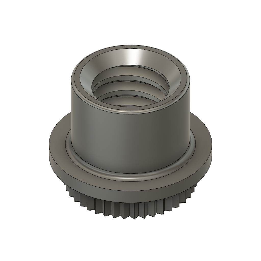
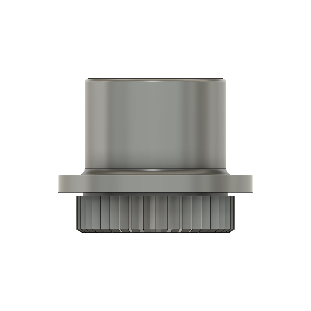
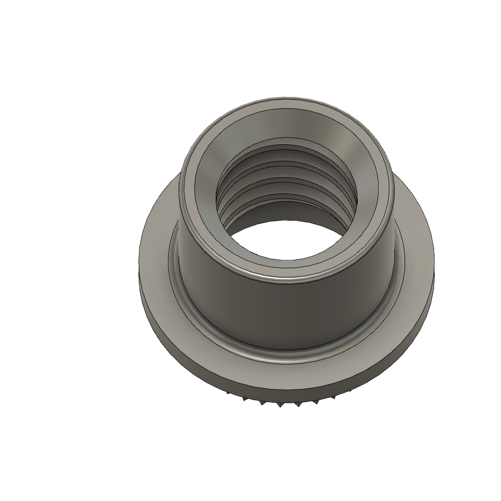
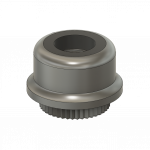
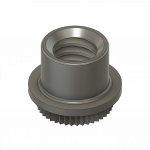
PART NUMBER:
NA2168
FEDERAL SUPPLY CODE:
32387
NA2168 Series Clinchnut / NASM45938/6
CLINCHNUT, SELF-LOCKING
MATERIAL:
-
NO CODE
Carbon steel, grade 1018 per ASTM A510/A510M, for sizes .0860 and .1120. Alloy steel grade 4130 per ASTM A322.
-
"S" CODE
CRES, type 303 per AMS5640, type I or type II.
-
"C" CODE
A286 corrosion resistant steel per AMS5731, ANS5732, AMS5734 or AMS5737.
-
"A" CODE
Alloy steel option for sizes .0860 and .1120 - alloy steel grade 4130 per ASTM A322.
FINISH:
-
NO CODE
Cadmium plated per AMS-QQ-P-416, type II, class 3. NAFCO molybdenum disulfide lubricant optional if nuts meet salt spray requirements of AMS-QQ-P-416, type II.
-
"S" CODE
Passivate per AMS2700, Method 1, class 4. NAFCO molybdenum disulfide lubricant optional.
-
"C" CODE
Passivate per AMS2700, method 1, class 4 or silver plate per AMS2410. NAFCO molybdenum disulfide lubricant optional
-
"A" CODE
Cadmium plated per AMS-QQ-P-416, type II, class 3. NAFCO molybdenum disulfide lubricant optional if nuts meet the salt spray requirements of AMS-QQ-P-416, type II.
SERVICE TEMP.:
-
NO CODE
To 450℉.
-
"S" CODE
To 450℉.
-
"C" CODE -- SILVER PLATED
To 800℉.
-
"C" CODE -- NON-SILVER PLATED
To 450℉.
-
"A" CODE
To 450℉.
VARIATIONS:
-
"M"
Add before first dash no. for optional dry-film lubricant.
-
"S"
Add before first dash no. for optional silver plate.
-
"DF"
Add after last dash no. for optional dry-film lubricant.
APPLICATION:
-
A press-in nut for use in thin aluminum and magnesium sheets, graphite composite and fiber-reinforced plastic sheets, printed circuit boards, etc.
Marketing Summary
PART #: NA2168
- Clinchnut
- Self-Locking
Notes:
- Under no circumstances will silver plating and solid film lubricant both be applied to A286 corrosion resistant steel.
- “M” finish code is equivalent to and supersedes “DF” finish code.
- For other finishes and materials contact NAFCO USA, LLC.
- Push-out and torque-out values shall be as specified in Table II when properly installed in low carbon steel sheet.
RECOMMENDED INSTALLATION PROCEDURE :
- Drill or punch hole in sheet (see Table II for sizes).
- DO NOT chamfer or deburr hole on side from which nut is inserted.
- Insert nut shank squarely in hole while supporting the structure. Place the punch (See figure 3 on page 4 of engineering spec sheets) on the nut crown and use a light hammer blow or small press to force the nut into the structure. The nut base must be fully and squarely seated against the structure.
- Using the punch to support the nut head, flare the shank outward using the correct tools (see figure 4 or figure 5 on page 5 of engineering spec sheets). DO NOT exceed the installation forces specified in Table II.
- Install the screw or bolt from the shank end of the nut.
