PART NUMBER:
NA2112
FEDERAL SUPPLY CODE:
32387
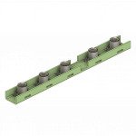
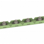
NA2112 Series Gang Channel / LE114-(0083-0100)
GANG CHANNEL, FLEXIBLE, VARIABLE COUNTERBORE, REPLACEABLE NUT ELEMENT, 160,000 PSI, 450℉
MATERIAL:
-
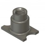
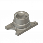
NUT
A286 CRES (UNS S66286) per AMS5525, AMS5732, or AMS5737.
-
CHANNEL
Aluminum alloy 7075-T6 or 7075-T62 (UNS A97075) per AMS-QQ-A-250/12.
-
RETAINING CLIP
XM-28 stainless steel spring wire (UNS S24100) per ASTM A313/A313M.
FINISH:
-
NUT
Passivate per AMS2700 plus NAFCO molybdenum disulfide dry film lubricant.
-
CHANNEL
Anodized per MIL-A-8625, type II, class 1 plus coat with AMS-C-27725, type II, grade 1 coating per NAFCO WI8.5-06.
-
RETAINING CLIP
Passivate per AMS2700 method 1 or 2.
CUTOFF CODE:
-
"-"
"U" cutoff at both ends.
-
V
"V" cutoff at both ends.
-
R
"U" cutoff at one end and "V" cutoff at the other end.
SERVICE TEMP.:
-
To 450℉.
PERFORMANCE:
-
NASM25027 except for torque-out and push-out, tensile 160,000 PSI at basic pitch diameter (see appropriate tables). These values apply both separately and combined. For push-out test, rivet spacing of a corresponding two-lug anchor nut will be applicable.


Marketing Summary
PART #: NA2112
- Gang Channel
- Flexible
- Variable Counterbore
- Replaceable Nut Element
- 160,000 PSI
- 450℉
Notes:
- Float of nut element shall not be less than .015 radially from centered position. Nut element shall be capable of engagement with a bolt in the maximum misaligned position.
- Bare channel ends resulting from channel being cut from larger sections permitted to be brush alodined per paragraph 3.3.8 of MIL-A-8625 or to be painted.
- /3/ Tolerances on channel apply before painting and all tolerances are non-cumulative.
- Dimensioning and tolerancing per ANSI Y14.5M-1982.
- Threads shall be in accordance with AS8879. The upper threaded portion of the nut shall be deformed to provide self-locking feature.
- /6/ Counterbore depth (“E” dimension) includes thickness of channel material.
- Channel will be readily bendable along minimum radius bends (see appropriate tables) with maximum permissible gap of .025 between channel and structure.
- Channel shall me marked with NAFCO USA, LLC manufacturing mark “N”. Location optional except must be visible after assembly.
- Nut element(s) shall be marked with manufacturer’s identification, first dash number (nut counterbore code) and “C” for CRES material in accordance with MIL-STD-130.