PART NUMBER:
NA1210
FEDERAL SUPPLY CODE:
32387
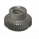
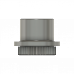
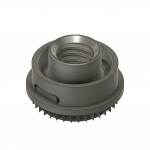
NA1210 Miniature Floating Jiffynut / NASM45938/13
NUT, PLAIN, CLINCH AND NUT, SELF-LOCKING, SELF-CLINCHING, KNURLED COLLAR, MINIATURE, FLOATING, 450 DEGREES FAHRENHEIT AND 600 DEGREES FAHRENHEIT
MATERIAL:
-
Alloy Steel
For use in materials with a hardness of 28 HRC max.
-
CRES
Type A286 (UNS S66286) per AMS5731, AMS5732, AMS5743 or AMS5737. For use in materials with a hardness of 90 HRB max.
FINISH:
-
Alloy Steel Nut and Retainer
Shall be cadmium plated per procurement specification.
-
Self-Locking CRES Element
Shall be silver plated per procurement specification.
LUBRICATION:
-
Alloy Steel Nut and Retainer
Solid film lubricant (solid film lubricant on retainer is manufacturer's option).
-
Self-Locking CRES Element
Solid film lubricant.
CODE:
-
Consists of the letter "M", the basic number of the specification sheet, a dash number taken from table I, and the letter "L" for self-locking nut or leave blank in non-locking feature.


Marketing Summary
PART #: NA1210
- Nut
- Plain
- Clinch and Nut
- Self-locking
- Self-clinching
- Knurled Collar
- Miniature
- Floating
- 400 Degrees Fahrenheit
- 600 Degrees Fahrenheit
Notes:
- Dimensions are in inches and apply after finish and prior to the application of lubrication unless otherwise specified.
- This standard takes precedence over documents referenced herein.
- Unless otherwise specified, part inventory manufactured to previous revisions of the applicable drawing or specification may be procured and used until stock is depleted.
- Referenced document shall be the issue in effect on date of invitations for bid.
- Threads shall be in accordance with AS8879 and shall apply before application of solid film lubricant. The upper portion of the nut element shall be deformed to provide self-locking feature.
- Push-out and torque-out values of alloy steel nuts shall be as specified in table II when properly installed in 6061-T6 aluminum alloy.
- /7/ Noted values represent nut element torquing-out of retainer portion of nut, retainer remains in parent material.
- Dimensioning and tolerancing per ANSI Y14.5M-1982.
Recommended Installation Procedures (See table II and figure 2):
- Drill or punch hole (CRES shall be drilled).
- Locate pilot squarely in hole. Use exit side of punched hole.
- Using a drive tool and anvil as shown in figure 2, apply sufficient force to cause a .015 inch minimum penetration into the structure for a full 360 degrees. Tool shown is a depth-stop type tool which installs nut to proper depth when tool bottoms against sheet surface. Use of nut manufacturer’s drive tool and anvil is mandatory.